
Last updated
11 min read
Arim Roll Mecha Engineering Team
01 / TORQUE BASIS
Separate coupling torque from motor torque
The adjustable value in a friction accumulation roller is normally the torque transmitted by its internal coupling. It is not the motor or gearbox output torque; drive ratio and efficiency convert it into tangential force at the roller surface.
Ideal tangential force at the roller surface equals transmitted torque divided by roller radius. For the same torque, a larger roller provides less surface force; for the same required force, a larger diameter requires more torque.
During accumulation, the coupling slips while each roller below the product continues to apply a small driving force. Excessive force increases load on the lead product and stop as well as friction heat and wear. Too little force causes stalls on contamination, cold starts, base irregularities or full-load restart.
Do not select the catalog maximum by default. Validate both reliable motion and safe accumulation under the worst product-base and environmental conditions.
02 / SELECTION WINDOW
The correct setting is a window, not one exact number
Tolerances, temperature, wear and product bases vary. Establish repeatable margin between the two operating boundaries rather than treating one calculation as a final setting.
Lower bound · convey and restart
Tset > TminMinimum torque required to move and restart the heaviest product under the worst base, temperature and contamination condition.
Operating setpoint · margin
Tmin < Tset < TmaxA setting that absorbs normal production variation while limiting line pressure and heat—not one that only just passes a single test.
Upper bound · accumulation limit
Tset < TmaxMaximum torque that keeps product, stop, roller temperature and drivetrain wear within limits during continuous accumulation.
03 / INPUT DATA
Inputs required before calculation
Mass alone cannot determine torque. Record the variables that change conveying resistance and accumulation behavior in the same operating scenarios.
| Input | What to record | Effect on torque |
|---|---|---|
| Product and base | Minimum and maximum mass, center of gravity, contact length, material, flatness, runners or feet | Sets rolling resistance and the effective number of rollers sharing force |
| Rollers and layout | Diameter, pitch, effective width, driven rollers below the load, coating or sleeves | Changes radius, load sharing, surface friction and torque required per roller |
| Motion profile | Speed, acceleration time, starts per hour, loaded restart, incline and direction changes | Adds acceleration and grade force and defines thermal duty |
| Accumulation case | Maximum queue, dwell time, allowable stop load and whether products may touch | Defines the upper torque boundary and minimum- versus zero-pressure choice |
| Transmission | Chain, belt or gear ratio, efficiency, motor and gearbox torque and current limits | Determines loss between calculated coupling torque and actual surface force |
| Environment and life | Temperature, oil, coolant, dust, washdown, wear state and inspection interval | Changes friction, torque spread, heat and readjustment interval |
04 / CALCULATION
Four steps to an initial torque
Equations narrow the candidate range. Whenever possible, pull the actual product slowly with a force gauge to measure rolling resistance, then correct the result through physical testing.
- 01
01 · Sum required tangential force
Add horizontal rolling resistance, grade force, acceleration force and external resistance from guides or seals. A pull test is more reliable than an assumed rolling coefficient.
- 02
02 · Determine effective driven rollers
Use rollers that actually contact the product base and transmit force, not every roller below it. Reduce the count for bow and installation-height tolerance.
- 03
03 · Calculate minimum torque per roller
Multiply total tangential force by roller radius, then divide by effective driven rollers and transmission efficiency. Keep units in N, m and N·m.
- 04
04 · Compare with the accumulation ceiling
Limit the combined force of slipping rollers using the allowable load on the lead product or stop. Measure lead pressure in the real queue.
05 / WORKED EXAMPLE
Initial selection example for a 200 kg carrier
This example demonstrates the method; it is not a selection result for a specific product. Repeat the test with the actual load and rollers.
Required tangential force
55 N + 30 N = 85 NA measured horizontal pull of 55 N plus 200 kg × 0.15 m/s² = 30 N for acceleration.
Minimum per roller
≈ 1.0 N·mWith 60 mm diameter, three effective driven rollers and 0.85 efficiency: 85 × 0.03 ÷ (3 × 0.85) ≈ 1.0 N·m.
Converted value
≈ 102 kgf·mmThe N·m value converted to kgf·mm. Compare it with supplier ranges and tolerances to choose candidates.
Assumed accumulation ceiling
≈ 1.5 N·m / rollerIf three rollers ideally share an allowable 150 N lead pressure: 150 × 0.03 ÷ 3 ≈ 1.5 N·m.
06 / FIELD VALIDATION
How to finalize torque on the conveyor
Following the logic of Hytrol's minimum-pressure adjustment, begin at low pressure that only just conveys the heaviest representative load, then add real production conditions step by step.
- 01
Measure actual resistance
Use a force gauge to record breakaway and running pull for the maximum load and worst product base at several conveyor positions.
- 02
Start with low torque
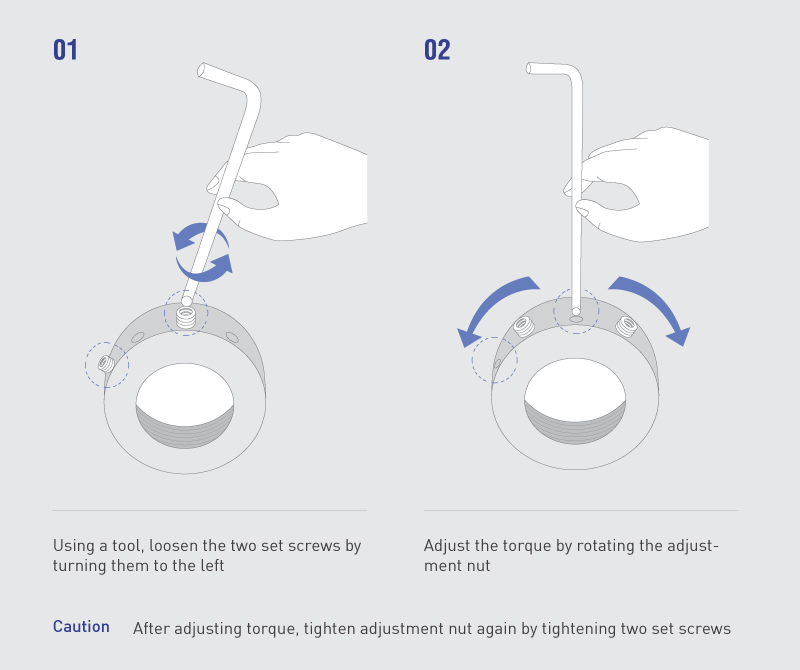
Lower the adjustment and increase it in small steps until the heaviest product moves. Follow the manufacturer's adjustment and locking procedure.
- 03
Validate restart and variation
Repeat full-load restart, light-product, reversed base, cold-start and contamination tests; observe slip, skew and hesitation.
- 04
Test the maximum queue
Accumulate the design quantity and record lead-product or stop force, contact marks and drivetrain current.
- 05
Run a thermal-duty test
Operate for maximum dwell and repeated cycles; trend roller, coupling and bearing temperature, odor, noise and wear debris.
- 06
Lock and document
Secure the final adjustment and record measured torque, turns, test conditions and acceptance band. Recheck after initial run-in.
07 / TROUBLESHOOTING
Field symptoms of an incorrect torque setting
Before increasing torque, inspect alignment, bearings, transmission and the product base as part of the same load path.
| Symptom | Possible cause | First check |
|---|---|---|
| Loaded restart fails or motion is intermittent | Torque below lower bound, fewer effective contacts, contamination or excessive guide resistance | Repeat pull test and check contacts, guides and efficiency before small adjustment |
| Stop impact or product compression | Torque above upper bound, longer queue, product friction or wrong accumulation method | Measure lead pressure; reduce torque or evaluate zero-pressure zones |
| Roller heat, odor or wear debris | Excess slip torque, long dwell, high duty or inadequate cooling | Trend temperature and dwell; verify duty rating and coupling condition |
| Large setting variation | Poor locking, wear, temperature or oil effects, or installation-height tolerance | Measure roller force under one test condition and define lock and replacement criteria |
08 / FAQ
Frequently asked questions
Q01Is more torque always more reliable?
It increases conveying margin, but also raises force on products and stops, friction heat and wear during accumulation. Select the lowest stable setting within the restart and accumulation boundaries.
Q02Can product mass alone determine torque?
No. Base material and flatness, roller diameter and pitch, effective contacts, speed, acceleration, incline, efficiency and environment are required. A pull test reduces uncertainty in rolling resistance.
Q03Can the same equation be used on an incline?
The gravity term m·g·sinθ can be added, but incline applications also require anti-slip, rollback, braking and product-stability analysis. Do not finalize safety from the friction equation alone.
Q04What if light and heavy products are mixed?
Test the heavy product's restart lower bound and the light product's contact and accumulation upper bound. If no common window exists, use zone-specific torque, another roller specification or zero-pressure control.
Q05How do kg·mm and N·m convert?
For the conventional kgf·mm torque unit, 1 N·m is about 101.97 kgf·mm. Confirm that the supplier uses kg·mm as shorthand for kgf·mm.